
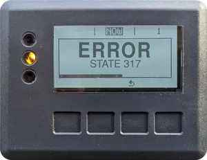
STATE 317
Unbalanced Intermediate Voltage
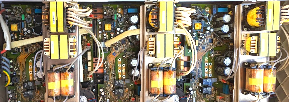
The inverter has detected that the DC-link (intermediate circuit) voltage is out of balance. This usually indicates stress or failure in the internal capacitor bank or power stage components
galvo
primo
symo
Expected Behaviors
- The inverter is displaying a STATE 317 message with a red or amber LED. Feed-in to the grid has been temporarily interrupted. The inverter will re-enter the startup phase and, if all self-tests pass, will resume normal operation automatically.
State Class
A state class is a generalized description of errors, catagorized by the number the STATE code starts with.
These errors cover thermal events, insulation resistance issues, and faults in power-conducting components like relays or contactors. These are usually safety-related and may cause the inverter to shut down to prevent hazards or damage. They may require active cooling improvements, inspection of wiring integrity, or hardware replacement. If the underlying condition clears, some errors may self-resolve; others will require intervention by a professional
- If this issue persists, it may be that the inverter has detected a fault within the external wiring and components, or an internal failure in the inverter. Further diagnosis, such as live circuit testing and internal inspection is required to troubleshoot further, which should only be performed by a trained Fronius Service Provider. Defective components or the inverter itself may require replacement.
Tips for Qualified Persons
The following procedures involve safety risks and potential for equipment damage. They are intended only for qualified personnel trained to identify and avoid the hazards that exist, and possess the appropriate PPE. These are general tips to aid professionals in troubleshooting, not instructions or directives to perform them.
We assume no liability for injury or damage resulting from their use.
- Leakage to ground may be present when a STATE 317 is displayed, proceed with caution. Metal surfaces that are not normally energized, may be if a fault exists. Inspect the DC circuits and grounding system thoroughly:
- Isolate DC circuits and measure insulation resistance between each conductor and ground. The value should not exceed the threshold set in the inverter (typically 1 MΩ), even in damp conditions.
- Check the continuity of the ground-fault fuse and replace if needed.
- If present, ensure the GFDI board is correctly connected.
- For IG inverters, verify the jumper position on the IG CTRL board is correct.
- Confirm that array grounding is properly bonded within the inverter.
- If all inspections and diagnostics have been completed and no resolution is found, it may be necessary to replace the faulty component, or the inverter itself. For advanced troubleshooting specific to your site, or to initiate a warranty claim, contact Fronius Technical Support at 1-877-Fro-nius (1-877-376-6487).
Fronius inverters in the U.S. typically come with a standard 10-year warranty. Starting in 2024, registering the inverter on the Fronius Solar.web website (the Fronius solar monitoring platform), extended the warranty by an additional 2 years, totaling 12 years of coverage, and updates the warranty start date to the actual installation date. Fronius has also offered warranty extensions of up to 20 years.
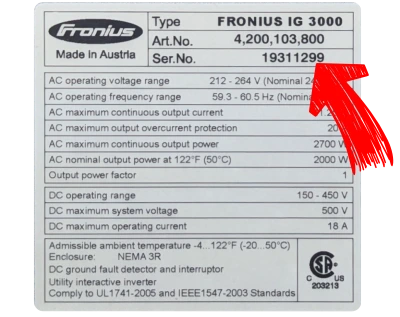
The inverter label, typically located on the bottom of the unit, lists the device serial number. To check if your inverter is still covered, call Fronius Technical Support at 1-877-Fro-nius (1-877-376-6487)
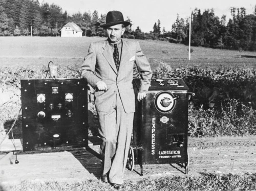
Founded in 1945 by Günter Fronius in Pettenbach, Austria, Fronius began as a repair shop for radios and electrical equipment. Recognizing the need for efficient battery charging, Günter developed a device to recharge car batteries, marking the company's first foray into energy solutions.
The best point of contact is your original installer
If the orginal installer is no longer available, contact a local Fronius Service Provider in your area.
Fronius Technical Support can also be reached at 1-877-Fro-nius (1-877-376-6487)
DENVER RESIDENTS: Is your system located in the Denver, CO metro area? CONTACT US
Comment
We have observed this error being due to a internal failure caused by too high of Amperage on the DC input. Review the inverter max MPPT input specification and the compare to the max possible array output using Isc and accounting for paralleled strings and excessive irradiance (x 1.56).