A ground fault in a solar PV system is one of the more common array issues to come across, especially in string inverter and commercial systems. Although they may not appear dangerous, they can be one of the more serious issues you’ll encounter. A ground fault occurs when a normally current-carrying electrical conductor, such as a positive or negative wire in a solar array, comes into contact with grounded metal components of the system, like the racking or conduit. This creates an unintended path to ground, potentially allowing current to leak or energize metal parts that shouldn’t be.
Luckily, most modern inverters actively monitor for ground faults and will shut down the system when one is detected. However, even when disabled, a ground fault still presents a fire or shock hazard if left unresolved.
How to Quickly Verify a Ground Fault Exists
In some cases, an inverter ground fault warning can be a false positive, or even caused by an internal failure in the device itself. The first step is to confirm whether an actual fault exists. The quickest way to do this is by isolating the DC circuits and measuring voltage from both the positive and negative conductors to ground using a multimeter.
In a properly operating system, both measurements should read zero volts, since the conductors are isolated from ground. It is important that these measurements are taken with both the positive and negative conductors in “free-air,” as depending on the system type, you may still get unexpected voltage readings to ground through fuses or GFDI devices. If either positive-to-ground or negative-to-ground shows significant voltage with the conductors in free-air, a ground fault is likely present, so use caution moving forward when locating the cause.
Why a Ground Fault Is Dangerous 🗲
A live ground fault means that one of the conductors is unintentionally energized with respect to the grounded metal framework. This can create a shock hazard and could result in arcing if another fault occurs on the opposite conductor.
In other words, metal surfaces that are not normally electrified, such as rails, conduits, and electrical panels, could be live and present a shock hazard until the fault is located. Electrical faults are invisible, so it’s easy to be complacent. Always wear your PPE, and remain mindful that there may be voltage where you do not expect it while a fault is present.
Locating a Ground Fault with a Multimeter
One reliable way to pinpoint the fault is by using simple voltage-to-ground measurements. In this example, we’ll use round numbers for illustration purposes. In the real world, the numbers may not be as precise, and they may not always add up exactly. Faults may not always be exactly between modules, and due to the capacitance effect of PV and changing temperatures, these values may float somewhat. Regardless, the procedure is as follows:
After isolating the affected circuit in free-air, measure:
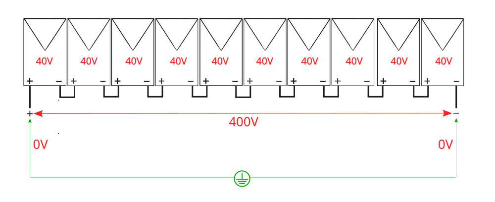
Positive to negative: This gives the total string voltage. By dividing this value by the number of modules in the string, you can also determine the individual module voltage. In this example, we have 10 modules and measured 400V from POS to NEG, so we know each module is about 40V.
Positive to ground and negative to ground: As shown above, these voltages should both be 0V in a healthy system, as neither the positive nor the negative conductors should be in contact with ground at any point in the array.
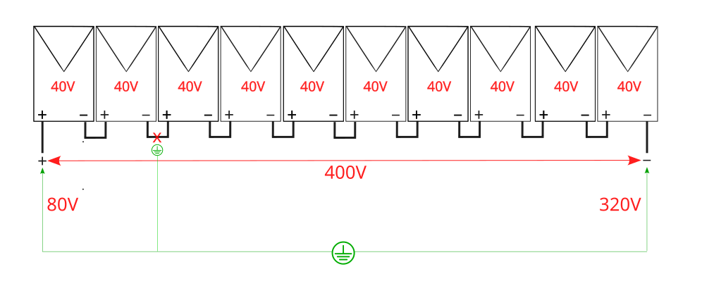
Ground Fault: If there’s a ground fault, you will read voltage from both positive and negative to ground, which will typically (but not always) be two different values. The two measurements will add up to the total string voltage. The difference gives you a clue where in the string the fault is located. For instance, if your total string voltage is 400V, and you read 80V from positive to ground and 320V from negative to ground, that indicates the fault lies roughly between the second and third module from the positive side.
You will still read the full voltage from positive to negative because all the modules are still connected (assuming the conductor isn’t broken). However, since the conductor between the second and third module is exposed and touching the ground, you now have potential to ground. Measuring from the positive side picks up just the first two modules upstream of the fault. Likewise, on the negative side between the fault and the negative homerun, you will see the voltage of the remaining 8 modules.
If you measure 0V from one side to ground and the full string voltage from the other, this indicates the fault is in one of the homeruns. For example, 400V from positive to ground and 0V from negative to ground could indicate the fault is in the negative homerun. Keep in mind, the values may not always be perfect, but they should still help narrow down the location of the fault. We’ve even found leakage inside the modules themselves, which can give more unusual readings, but following these steps still helped locate the issue.
Verifying the Fault: This step isn’t necessary but can help illustrate conditions during a ground fault. It can also be used to verify what you’re measuring, help locate the affected string, or identify which side the fault is on.
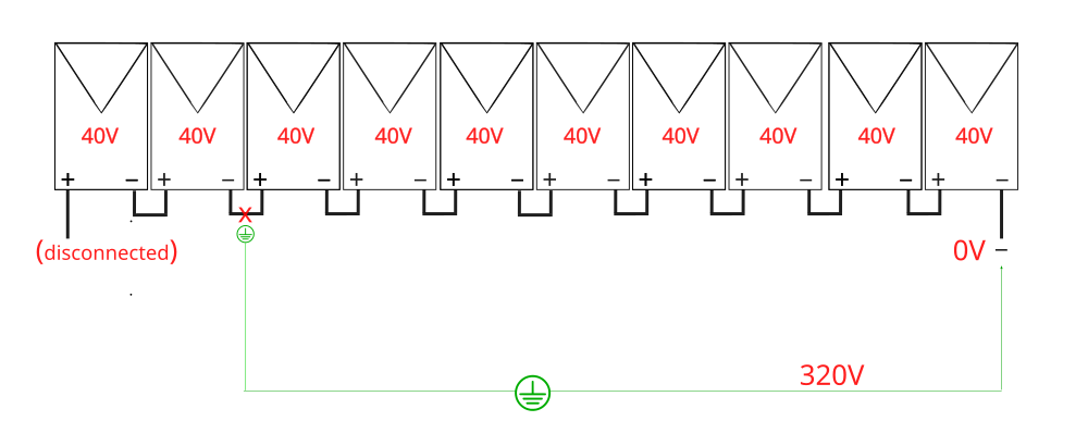
In the previous example, with a ground fault between the second and third module, we still read 400V from positive to negative as they were both still connected. Let’s say you disconnect the MC4 on the positive end of the string. As expected, you would see 0V from positive to negative since the circuit is open. However, you may be surprised to still read 320V from negative to ground. That’s because the ground wire is now completing the circuit through the fault. This illustrates just how dangerous a ground fault can be. This technique is useful to verify that you’re seeing a real ground fault, that you’re inspecting the correct string, and to reinforce where the fault is located in reference to the homeruns.
Now, let’s walk through a real-world example of this process in action so you can see how we use this to locate and repair a ground fault.
Real Case Study Example
We were called out to investigate a fault on a residential system using a Fronius string inverter. Upon arrival, we observed the STATE 475 message on the display, indicating a ground fault had been detected in the array.
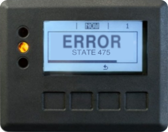
Step 1: Confirming the Fault
The first thing we did was confirm there was an actual fault and not an issue internal to the inverter. We isolated the single circuit entering the inverter and measured voltage to ground. Both the positive and negative showed voltage to ground, confirming there was a live ground fault.
Step 2: Isolating the string
Tracing the conduit back to the array from the inverter, we found that although there was only one circuit connected, it was actually the output of two strings, combined in a junction box on the roof.
We accessed the combiner, and disconnected both strings individually. Testing each one in free-air, we found the faulted string by identifying which one showed voltage to ground, and left the other disconnected to remove it from the troubleshooting process. The measurements for the affected circuit are rounded here to make it easier to follow along, though the real-world readings were slightly different. The readings were as follows:
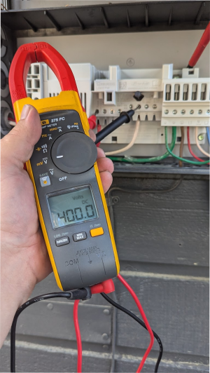
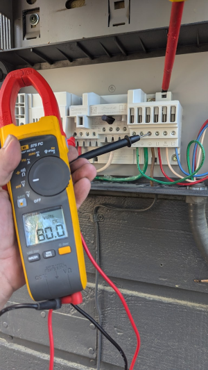
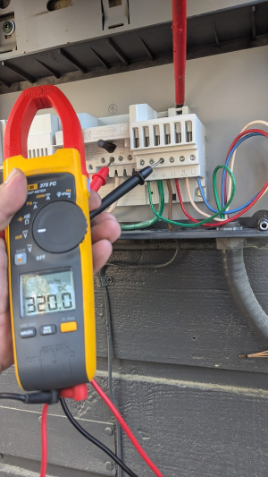
The total array was 20 modules, so with two even strings, we knew this circuit had 10 modules in series. With 400V from positive to negative, we knew each module was around 40V. Seeing 80V from positive to ground and 320V from negative to ground told us the ground fault was between the second and third module from the positive homerun connection.
Step 3: Locating the Affected String
To confirm which homerun belonged to this string, one technician monitored the positive-to-ground voltage at the combiner box while another began disconnecting the positive homeruns at the array. When we reached the affected string, the positive-to-ground voltage dropped to zero, confirming we had the right one. Even with the positive disconnected, we still measured 320V from the negative conductor to ground, further confirming the fault downstream of the positive homerun.

Step 4: Physical Inspection and Repair
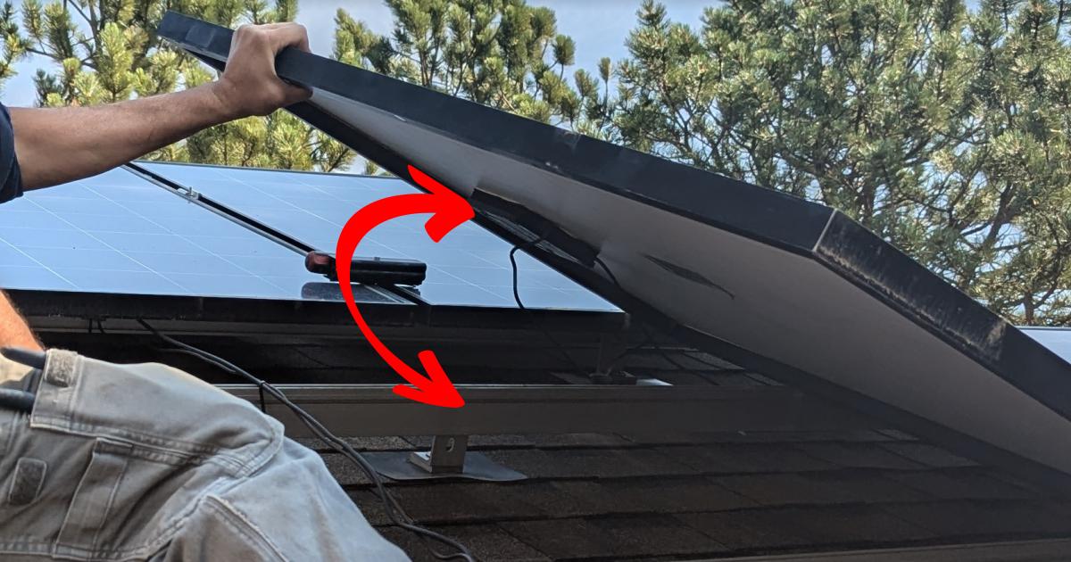
We lifted the third module in the string and found the issue: a pinched wire between the module’s larger-than-normal junction box and the aluminum rail, located exactly between the second and third module, just as expected. This saved us significant trial-and-error time. The conductor had been pinched during a previous remove-and-reinstall and eventually damaged the insulation about a year later, allowing contact with the rail.
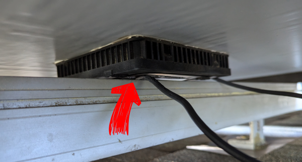
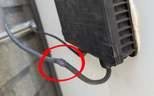
We repaired the fault by cutting out the damaged section of wire and crimping in a new MC4 connector.
Step 5: Verifying System Health
After the repair, we tested both strings using an insulation resistance meter (megohmmeter). Each string measured over 200 MΩ to ground at 1000V DC, confirming there were no other ground faults or potential future issues.
With the fault resolved and all strings confirmed healthy, we reconnected the inverter and brought the system back online. Using this method, it took longer to set up the ladder than it did to locate and repair the issue.
Final Thoughts
Ground faults can be tricky and potentially dangerous, but with the right tools and methodical troubleshooting, they can be identified and resolved quickly. Using basic voltage measurements and understanding how those readings translate to a physical location in the array can save hours of trial and error. And while this method doesn’t require a megohmmeter to locate the fault, it’s always good practice to use one after repairs to ensure long-term reliability.
This case is a great reminder of the importance of attention to detail during installation, and how effective teamwork and good technique can bring a system safely back online.
